![[팰콘샵] [Matek] 마텍 AP_Periph CAN Node (CAN-G474)](/shop/data/goods/1755729472329.jpg)

 Virtual Assistant
상품상세설명
믿을 수 있는 팰콘샵, 6가지 안심 약속
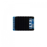
Matek AP_Periph CAN Node CAN-G474
구성
CAN-G474 보드 1개
JST-GH-4P ~ JST-H-4P 20cm 실리콘 와이어 2개
JST-GH-6P ~ JST-GH-6P 20cm 실리콘 와이어 1개
![[팰콘샵] [Matek] 마텍 AP_Periph CAN Node (CAN-G474)](https://www.susungrc.com/web/upload/NNEditor/20250807/CAN-G474_3.jpg)
CAN-G474 is an Adapter Node based on ArudPilot AP_Periph firmware.
with 5Mbit/s CAN transceiver and STM32G474 MCU, CAN-G474 is capable of CANFD.
With this board, you can easily utilize the ArduPilot driver library to convert ArduPilot supported GNSS, Compass, Barometer, Airspeed sensor,
Rangefinder, Proximity sensor, Electronic Fuel Injectors and GPIO based (PWM, LED notify) peripherals to DroneCAN bus peripherals.
Specifications
MCU: STM32G474CE, 512KB Flash
CAN transceiver data rates up to 5Mbit/s
2x CAN bus
4x UARTs
for peripheral GNSS, Rangefinder, Proximity, EFI, RC input(receiver)
support GNSS, Compass, Barometer sensors over MSP protocol. MSP is enable on TX3 by default.
2x I2C bus
for peripheral I2C Airspeed sensor, Barometer, Compass
1x SPI
for peripheral RM3100
SPI pads for RM3100 are on bottom side, with “CS, MOSI, MISO, SCK” silkprint
11x PWM outputs
for Servos and ESC, all PWMs support DMA/DShot
PWM1-10 on DuPont 2.54mm holes
PWM11 pad is on bottom side, with “11” silkprint
ST debug, SWC & SWD(on bottom side)
UART1(TX1,RX1) support firmware update in DFU mode
LED
Blue, Fast blinking, Booting
Blue, Slow blinking, communicating with flight controller
Red, 3.3V indicator
Input voltage range: 4.5~5.5V @5V pad/pin
Power consumption: 62mA
Operating Temperatures: -30~85 °C
Physical
5x JST-GH-4P(SM04B-GHS-TB) for CAN1, CAN2, I2C1, UART1 and UART4
1x JST-GH-6P(SM06B-GHS-TB) for UART3+I2C2
18x DuPont 2.54mm holes
Board Size: 36mm*36mm*6mm. 5.2g,
Mounting: 30.5mm 4x Dia.3mm
3D file : CAN-G474_STEP.zip
Packing
1x CAN-G474 board
2x JST-GH-4P to JST-GH-4P 20cm silicon wire
1x JST-GH-6P to JST-GH-6P 20cm silicon wire
Firmware
ArduPilot AP_Periph MatekG474-Periph for peripheral sensors
ArduPilot AP_Periph MatekG474-DShot for DroneCAN-PWM output
Update via DroneCAN GUI Tool or Mission Planner-DroneCAN Tab, load "AP_Periph.bin"
Update via STM32CubeProgrammer in DFU mode, connect USB-TTL module to UART1, Plug USB while holding the DFU button in, load "AP_Periph_with_bl.hex".
Note
Just need to connect either one CAN bus to flight controller, or connect both to FC for redundancy.
SWC/SWD share MCU pins with SDA1/SCL1
Other MCU pins not specified are useless for now.
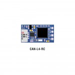
CAN-G474 support 1Mbit ~ 5Mbit CAN/CANFD, CAN-L431 works with 1Mbit CAN.
![[팰콘샵] [Matek] 마텍 AP_Periph CAN Node (CAN-G474)](https://www.susungrc.com/web/upload/NNEditor/20250807/CAN-G474_4.jpg)
| AP_Periph fw MatekG474-Periph | |||||
| CAN | CAN1-H / CAN1-L | CAN1 | CAN1_PROTOCOL | 1 | |
| CAN2-H / CAN2-L | CAN2 | CAN2_PROTOCOL | 1 | ||
| UART | TX1 / RX1 | USART1 DMA | Serial PORT 1 | RC_PORT | 1 |
| TX2 / RX2 | USART2 DMA | Serial PORT 2 | GPS_PORT | 2 | |
| TX3 / RX3 | USART3 NODMA | Serial PORT 3 | MSP_PORT | 3 | |
| TX4 / RX4 | UART4 DMA | Serial PORT 4 | RNGFND_PORT | 4 | |
| PRX_PORT | -1 | ||||
| EFI_PORT | -1 | ||||
| I2C | CL1 / DA1 CL2 / DA2 | I2C1 I2C2 | BUS0 BUS1 | BATT_MONITOR BATT_I2C_BUS | 21 0 |
| ARSPD_TYPE | 0 (none) 1 (MS4525) 9 (I2C-DLVR-10) | ||||
| COMPASS_ENABLE COMPASS_DISBLMSK | 1 0 | ||||
| SPI | CS /MOSI /MISO /SCK | RM3100 | |||
| Disable GPS | GPS_PORT | -1 | |||
| Disable compass | COMPASS_ENABLE | 0 | |||
| Disable Battery monitor | BATT_MONITOR | 0 | |||
| Disable MSP | MSP_PORT | -1 | |||
| * | * | * | * | * | * |
| AP_Periph fw MatekG474-Dshot | |||||
| PWM | 1 | Group 1 | TIM2_CH1 | OUT1_FUNCTION | 33 |
| 2 | TIM2_CH2 | OUT2_FUNCTION | 34 | ||
| 3 | TIM2_CH3 | OUT3_FUNCTION | 35 | ||
| 4 | TIM2_CH4 | OUT4_FUNCTION | 36 | ||
| 5 | Group 2 | TIM3_CH1 | OUT5_FUNCTION | 51 | |
| 6 | TIM3_CH2 | OUT6_FUNCTION | 52 | ||
| 7 | TIM3_CH3 | OUT7_FUNCTION | 53 | ||
| 8 | TIM3_CH4 | OUT8_FUNCTION | 54 | ||
| 9 | Group 3 | TIM8_CH1 | OUT9_FUNCTION | 55 | |
| 10 | TIM8_CH2 | OUT10_FUNCTION | 56 | ||
| 11 | Group 4 | TIM5_CH1 | OUT11_FUNCTION | 57 | |
| ESC_TELEM_PORT | 3 | ||||
| ESC_PWM_TYPE | 7 | ||||
| OUT_BLH_OTYPE | 6 | ||||
| OUT_BLH_MAS | 15 | ||||
Flight controller Parameters for sensors
CAN_D*_PROTOCOL = 1
CAN_P*_DRIVER = 1
GPS*_TYPE = 9 DroneCAN
COMPASS_TYPEMASK = 0 (DroneCAN Unchecked)
ARSPD*_TYPE = 8 (DroneCAN)
BATT*_MONITOR = 8 (DroneCAN)
RNGFND*_TYPE = 24 (DroneCAN)
EFI*_TYPE = 5 (DroneCAN)
PRX*_TYPE = 14 (DroneCAN)
Flight controller Parameters for PWM
CAN_D*_PROTOCOL = 1
CAN_P*_DRIVER = 1
CAN_D*_UC_ESC_OF = 4 (Plane 4.2.1 or newer)
CAN_D*_UC_ESC_BM = x
CAN_D*_UC_SRV_BM = x
BRD_SAFETYENABLE = 0 (if your flight controller doesn’t have safety pin)
Tutorial : Using MatekL431 adapters for PWM and DShot