① 99.9% 실재고 관리매일 밤 자동 갱신, 유령 재고 NO! 보이는 수량이 진짜입니다.
② 22년 전문가 직답국내 최고 전문가가 막힘없이 즉시 해결해 드립니다.
③ 확실한 기술 지원국내 최고 수준의 노하우로 막힘없는 솔루션을 제공합니다.
④ 출고 전 전수 촬영출고 전 제품 사진 기록으로 오배송 및 누락을 원천 차단합니다.
⑤ 실시간 배송 일정주문 확인 즉시 발송 예정일을 카톡으로 먼저 알려드립니다.
⑥ Since 2004 신뢰22년을 한결같이 지켜온 믿음. 걱정 없이 이용하세요.
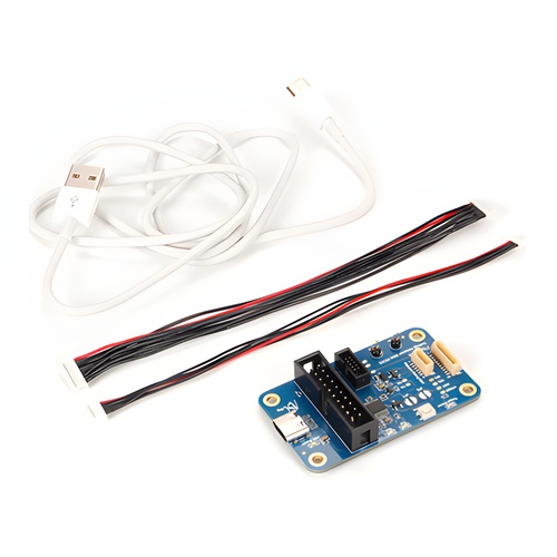
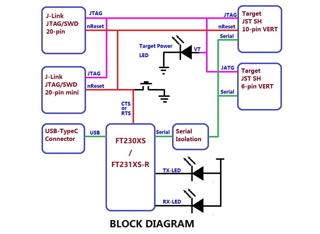
The Pixhawk Debug Adapter provides a JTAG SWD and Serial interface to debug Pixhawk compatible hardware. Both the Target 6-pin (FMUV5) and Target 10-pin (FMUVxX) Pixhawk debug connector standards are supported.
The built-in FTDI serial interface eliminates the need for a separate FTDI cable. The interface is specially designed to not backfeed the FMU, thus ensuring stable and reliable debugging regardless of power sequencing.
Two Host JTAG interface standards are supported: The 10-pin ARM compatible with the Segger Jlink-mini and 20-pin compatible with the Segger Jlink or STLink.
The adapter also provides easily accessible ground points. When used with the 10-pin target cable it further supports two GPIO from the CPU that can be used to perform accurate signal timing. Target Reset via a push button, JTAG or optionly RTS from the serial interface is also supported over the 10-pin target interface.
Jumperable Options:
JP1 - Normally Open. - Soldering this closed will bypass the RXD_DEBUG Back-feeding protection diode. This should not be needed unless the target already has the Back-feeding protection diode AND the target is not receiving data due to signaling levels.
JP2 - Normally Open. Soldering this closed will connect the RTS signal from the HOST to the CPU nRST line. With this jumper soldered, the CPU nRST will be wired OR of the reset Button, the JTAG reset and the HOST RTS line. With it open the HOST RTS line is not connected. This could be used on automated test racks.